PITOT-STATIC
PROPERTIES & CHARACTERISTICS
MACH NUMBER RANGE
The lower usable limit for Pitot-Static probes
depends on the sensitivity
of the readout device
used with the probe. A differential
pressure of 1"
of water, for example is about the minimum that
can
be measured with 1% accuracy with ordinary
slant gauges, so the lower limit
is approximately at
a Mach Number of 0.06 or velocity of 70 ft/sec for
air at standard atmospheric conditions. While
there is no
minimum Mach Number for the probe
itself, there are viscous drag effects
that should be
considered when using a probe in a low velocity
fluid
field. (See Reynolds Number Range). The
upper limit is at about
Mach 0.95 for the total
pressure reading and 0.70 for the static as
shown
in Figure 1. The static reading is accurate to 0.5%
to
a Mach Number of 0.50 and to 1.5% up to Mach
0.70. At this point the
calibration becomes erratic
due to the formation of local shock waves on
and
around the tip of the probe and the reading can
vary as much
as 10% with slight changes in flow
conditions or proximity to solid boundaries.
Above Mach 1.0 both the total and static readings
vary considerably
from true stream values but
they can be corrected theoretically.
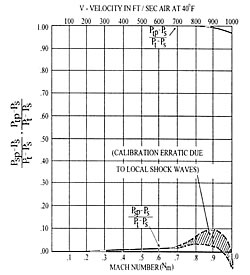
Figure 1. Mach Number Range.
| Pt | Total pressure (impact / stagnation pressure) |
| Ps | Static pressure (ambient / stream pressure) |
| Ptp | Indicated total pressure |
| Psp | Indicated static pressure |
BOUNDARY EFFECTS
The static pressure indication is sensitive to
distance from solid
boundaries. Figure 3 shows
how this error increases the indicated
velocity
pressure at a Mach Number 0.25. The probe and
boundary
form a Venturi passage, which
accelerates the flow and decreases the
static
pressure on one side. The curve shows that static
readings
should not be taken closer than 5 tube
diameters from a boundary for
1% accuracy and 10
tube diameters is safer.
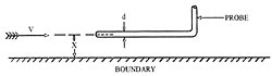
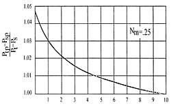
Figure 3. Boundary Effects.
REYNOLDS NUMBER RANGE
Pitot-Static probes are not directly affected by
Reynolds Number
except at very low velocities.
Therefore, in liquids where compressibility
effects
are absent, their calibration is substantially
constant
at all velocities.
The minimum Reynolds Number for the total
pressure measurement is about 30 where the
characteristic length is
the diameter of the impact
hole. Below this value the indicated impact
pressure becomes higher than the stream impact
pressure due to
viscosity effects. This error is only
noticeable in air under standard
atmospheric
conditions for velocities under 12 ft/sec with impact
holes 0.010" diameter or less.
YAW AND PITCH ANGLE RANGE
If the fluid stream is not parallel to the probe head, errors
occur
in both total and static readings. These are the most
important
errors in this type of instrument because they
cannot be corrected without
taking independent readings
with another type of probe.
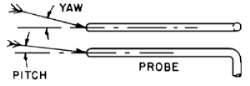
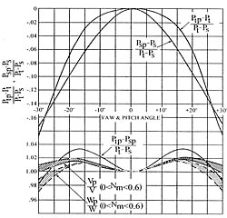
Figure 2. Yaw and Pitch Angle Error.
| VP | Indicated velocity calculated from Ptp and Psp using standard equations. |
| W | Weight flow rate - lbs. sec x ft² |
| Wp | Indicated weight flow rate from Ptp and Psp |
Note that yaw and pitch angle affect the readings
exactly the same. The errors in total and static pressure increase quite rapidly for angles of attack higher than 5°, but they tend
to compensate each other so the probe yields velocity and weight flow
readings accurate to 2% up to angles of attack of 30°. This is the
chief advantage of the Prandtl design over other types.
TURBULENCE ERRORS
Pitot-Static tubes appear to be insensitive to isotropic
turbulence,
which is the most common type. Under some
conditions of high
intensity, large scale turbulence,
could make the angle of attack at a probe
vary over a
wide range. This probe would presumably have an error
corresponding to the average yaw or pitch angle
produced by the turbulence.
TIME CONSTANT
The speed of reading depends on the length and
diameter of the
pressure passages inside the probe, the
size of the pressure tubes to the
manometer, and the
displacement volume of the manometer. The time
constant is very short for any of the standard tubes
down to 1/8" diameter;
however, it increases rapidly for
smaller diameters. For this
reason 1/16" OD is the
smallest recommended size for ordinary use - this
will
take 15 to 60 seconds to reach equilibrium pressure with
ordinary
manometer hook-ups. These tubes have been
made as small as
1/32" OD, but their time constant is as
long as 15 minutes and they clog
up very easily with fine
dirt in the flow stream. If very small tubes
are required, it
is preferable to use separate total and static tubes
rather
than the combined total-static type. Where reinforcing
stems are specified on small sizes, the inner tubes are
enlarged at the
same point to ensure minimum time
constant.
INSTALLATION INFORMATION
Probes are installed in the fluid stream with the impact
hole facing
upstream, the head parallel to the flow
direction and the stem perpendicular.
Types PA and PB
(Fig. 4) are well suited to mounting on
thin - walled ducts
where the probe is to be inserted from the outside.
Types PC and PD (Fig. 5) are designed with removable
pressure take-offs.
This allows for installation from
within the duct where it is not practical
to make an
insertion hole diameter equal to the length of the probe
tip. Figure 6 shows a correlation between probe diameter
and minimum
wall insertion dimensions for a probe with
fixed take-offs.
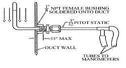
Figure 4. Thin wall installation.
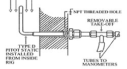
Figure 5. Thick wall installation.