GAS SAMPLING PROBES
General Information
United Sensor Gas Sampling probes have been designed for accurate sampling of burner exhaust gases primarily used in efficiency studies of combustion and they have been endurance tested in routine test work.
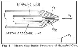
An internal
static tap is located in the inner flow
passage of the probe near the sample
inlet as
shown in Fig. 1 so the static pressure of the
sampled
gas can be measured. In order to obtain
a true sample, it has been
found necessary to draw
off the gas at the same velocity as is flowing
in the
duct. If the sample is accelerated or decelerated as
it
is drawn into the probe, it will not be a true
average since, in the first
case, a disproportionate
share of low density components will be drawn
in,
and in the second case, too much of the high
density components
will be sampled.

This would not be true in a perfectly homogeneous mixture of gases, but in the region most sampling is done the mixture is not homogeneous since the fuel particles are usually still burning or have just completed burning and the products of combustion are concentrated in "slugs" of gas interspersed by lighter, unburned air.
The gas velocity in the duct is proportional to:

Where Pt, Ps, and d are total pressure, static
pressure, and density, and K
is a constant.
The gas velocity in the probe inlet is proportional
to:
Pt1 will automatically equal Pt2 since no work is done on the gas in drawing it into the probe so if Ps1 is made equal to Ps2 it can be seen that V1will equal V2. Since the static pressures are equal and there is no change in temperature, d1 and d2 will also be equal.
By measuring the static pressure Ps1 with a static tap in the wall of the duct at the same cross section and Ps2 with the internal static tap on the probe, the two can be equalized by adjusting the sampling< suction.
In some cases, the resulting volume of gas flow through the sample probe is too high or too low for the gas sampling apparatus. The orifice inlet diameter is picked to be high enough to give a flow at the lowest duct velocity V1 sufficient for analysis purposes and the excess gas sampled at higher duct velocities is by-passed around the analyzer by a bypass line and valve.
