DIRECTIONAL PROBES
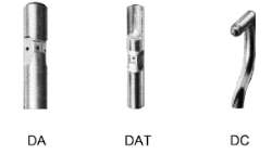
3-Dimensional Probes
United Sensor 3 Dimensional Directional probes measure yaw and pitch angles
of fluid flow, as well as total and static pressures and total temperature.
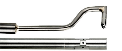
Each probe has five measuring holes located on its tip.
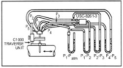
A centrally located pressure hole measures pressure P1, while two lateral pressure holes measure pressures P2 and P3. If the
probe is rotated by a Traverse Unit (Fig. 1) until P2 = P3 as indicated on a manometer or other sensitive
pressure indicator, the yaw angle of flow is then indicated by the traverse unit scale (see Manual Traverse Unit ).
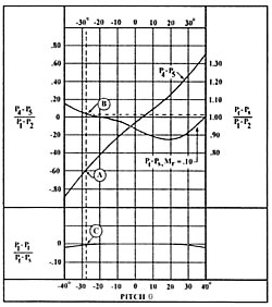
When the yaw angle has been determined an additional
differential pressure P4 - P5 is measured by pressure holes located
above and below the total pressure (P1) hole. Pitch angle is
determined by calculating (P4 - P5)/ (P1 - P2) and using the calibration
curve for the individual probe (e.g. Curve A, Figs. 2 and 3).
At any particular pitch angle the velocity pressure coefficient (Pt
- Ps)/ (P1 - P2) and total pressure coefficient (P1 - Pt)/ (Pt - Ps) can be read from curves B and C, while Pt - Ps and Ps can be calculated.
In the case of Type DAT probes, a half
shielded thermocouple
sensor at the probe tip provides total temperature
measurements
at the same point in the stream as fluid pressure and flow direction measurements.